Monday, 3 April 2017

Capacitors are your friend - but how much of a friend?

On one hand I agree, when dealing with large momentary current draw, capacitors are your friend. This I agree with. However using this phrase without knowing the details of the circuit or limitations is just plain stupid. There comes a point of diminishing returns.

GSM applications are a great example of dealing with large currents for a short period of time. Most GSM modules can pull up to 2A for a very short period of time before dropping back down to a nominal current draw in the milli-Amp range. As the nominal current draw is in the in milli-Amp range, we don't necessarily need a power supply that can supply 2A all the time. This would be expensive and bulky. In this case, capacitors can be charged to store this energy when it is needed. This is a typical application of when the phrase "capacitors are your friend", applies.

It's not quite as simple as adding a bunch of 100uF capacitors and we should be alright. Usually when a large current draw is necessary, we get an inductor effect. The device will try pull this power, if it can't supply this power, it will caus the voltage to drop, to try and meet this current. Once the voltage drops below a certain level, our circuit, microcontrollers and other devices will stop working. We absolutely do not want this to happen.

In order to stop this from happening, we need to know three things:
  1. How much energy is needed
  2. How quickly this current draw is needed
  3. How often it is needed
How much energy is dictated by the voltage, the current and the duration of the current pulse.

How quickly we need it dictates our ESR (equivalent series resistance) of the capacitor. The larger the resistance, the slower it will provide this stored energy. It's also important to note, the lower the resistance, the more expensive the capacitor.

How often is it needed tells us if we have enough time to charge the capacitor(s) before the next current pulse. While expecting the capacitor to discharge with the current pulse, we often forget the capacitor has to charge back up again in time for the next pulse.

We also need to know what our power supply can handle as this dictates our charge time. 

The GSM modules are a great example of a case where capacitors are your friend. The 2A pulse happens only for a very short amount of time (~2ms). Using the following equation:

C = t x I / V

Where C is our capacitance, t is the duration of the spike, I is our current spike and V is the acceptable voltage drop. A greater acceptable voltage drop, will allow for a smaller capacitor. For the current, we're specifically interested in the current above what our power supply can provide. Let's assume a 500mA supply.

t = 0.002 seconds (2ms)
I = 2 Amps - 500mA = 1.5 Amps
V = 0.5 Volt

C = 0.002 x (1.5 / 0.5) = 0.006 Farads = 6mF


In the world of IoT, I'm currently working with Sigfox. While I have no problems with the European (RCZ1) products that need a 50mA pulse, it's the US/AUS/NZ (RCZ2 and RCZ4)  that need a much larger current pulse (250mA) that provide a problem

Taking the European Sigfox, a 3.6V Lithium Thionyl Chloride C Cell battery can provide up to 100mA without problems. The transmission time is a little longer at 6 seconds for 3 transmissions. I'm working with 6 seconds here as there isn't really any time for a capacitor to charge to full again in between each transmission. The following equation assumes the battery can't supply the 50mA. 

t = 6 seconds
I = 0.05 Amps
V = 0.5 Volts

C = 6 x (0.05 / 0.2) = 0.6 Farads 
(this seems large, but the battery can easily handle this, so we don't care)

Now, let's take the same battery for the US/AUS/NZ networks. The current draw is larger than what the battery can supply. The transmission time is shorter, but the current is larger. 

t = 3 seconds
I = 0.250 Amps - 0.1 Amps (supplied from the battery) = 0.15 Amps
V = 0.5 Volts

C = 3 x (0.150 / 0.5) = 0.9 Farads

We can see that we need 0.9 Farads of capacitance to ensure no more than 0.5 Volt drop over 3 seconds with a battery providing 100mA. Compare this to the GSM module, this means a capacitor 150 times larger for the Sigfox solution. I'll admit, this isn't quite what I was expecting from something that advertises itself as a low power wireless evolution. That's even assuming 0.5 volt drop is acceptable, which in most cases, it won't be. 0.2 Volt drop is more acceptable, but this increases the needed capacitance to 2.25 Farads. With an ESR below 1 ohm, this capacitor will be both large and costly to the product. 

While Capacitance is your friend, it is subject to diminishing returns. In GSM applications, capacitance will help you without affecting costs too much. In the case of US/AUS/NZ Sigfox applications, a larger battery with better current handling is necessary alongside some smaller bulk and decoupling capacitance to ensure sufficient power when you need it.


Wednesday, 8 June 2016

EPE: PIC Microcontrollers and the PICkit 3: A beginner's guide – Part 2


This month, is part 2 of an ongoing series going back to basics for PIC Microcontrollers and the PICkit3.

Over the coming months, I'll be covering everything from the difference between microcontrollers and microprocessors to Microchip's MPLAB X IDE, the PIC Low Pin Count Demo Board and the incredibly useful PICkit3 programmer tool. I hope to build a strong foundation of understanding for microcontroller programming and project design.

This month I take a look at Microchip's MPLAB X IDE. This integrated development environment allows us an easy allow in one package that allows us to write and compile our code, manage our projects and libraries, as well as program and debug our PIC microcontrollers from a single visual platform. This is the tool for designing any PIC project.

If you've always to give PICs a try, but didn't know where to start, then I recommend checking out last months article in Everyday Practical Electronics.

You can buy the latest edition in PDF format online at http://www.epemag.com/buy-epe-online.html or you can buy it off from the shelf in your nearest newsagents.

To follow along with the articles, I recommend getting your hands on the following:
1. Purchase the PICkit 3 Low Pin Count Demo Board (http://tinyurl.com/h2jj2ek)
2. Purchase the PICkit 3 Programmer + USB Cable (http://tinyurl.com/zcpx3le)
3. Download PICkit 3 Starter Kit User’s Guide (http://tinyurl.com/jyqfeuk)
4. Download MPLAB X IDE (http://tinyurl.com/hmehqja)
5. Download XC8 Compiler (http://tinyurl.com/h5g9k5l)


I can't fit everything in the article, so whatever extra I have, might end up here on my blog page. So be sure to check back regularly for more cool projects.

Next month, I'll be getting my hands dirty with some lessons and some coding, based off the PICkit3 Starter Kit User Guide from Microchip's website. It's a decent PDF, but if you're new to PICs, then it can be a minefield.

Wednesday, 11 May 2016

EPE: PIC Microcontrollers and the PICkit 3: A beginner's guide – Part 1


This month, I start an ongoing series going back to basics for PIC Microcontrollers and the PICkit3.

Over the coming months, I'll be covering everything from the difference between microcontrollers and microprocessors to Microchip's MPLAB X IDE, the PIC Low Pin Count Demo Board and the incredibly useful PICkit3 programmer tool. I hope to build a strong foundation of understanding for microcontroller programming and project design.

This month I look at the difference between microcontrollers and microprocessors, as well as Raspverry PI's, Arduino's and PICs.

If you've always to give PICs a try, but didn't know where to start, then this month is a great time to subscribe to Everyday Practical Electronics and read my monthly PIC n MIX articles.

You can buy it in PDF format online at http://www.epemag.com/buy-epe-online.html or you can buy it off from the shelf in your nearest newsagents.

To follow along with the articles, I recommend getting your hands on the following:
1. Purchase the PICkit 3 Low Pin Count Demo Board (http://tinyurl.com/h2jj2ek)
2. Purchase the PICkit 3 Programmer + USB Cable (http://tinyurl.com/zcpx3le)
3. Download PICkit 3 Starter Kit User’s Guide (http://tinyurl.com/jyqfeuk)
4. Download MPLAB X IDE (http://tinyurl.com/hmehqja)
5. Download XC8 Compiler (http://tinyurl.com/h5g9k5l)

I can't fit everything in the article, so whatever extra I have, might end up here on my blog page. So be sure to check back regularly for more cool projects.

Friday, 8 January 2016

Software Management


It's the new year, make a resolution you can keep and get on top of Software Management.

Check out my latest PIC N Mix column in Everday Practical Electronics where I talk about everything in Software Management from Compilers to IDE's, Repositories, Version Control and Bug Tracking.

You can buy it in PDF format online at http://www.epemag.com/buy-epe-online.html or you can buy it off from the shelf in your nearest newsagents.

Unfortunately not all of it makes it to the article, so check out the following links for more info:

1) Best Bug Tracking Software of 2015 - Capterra
2) List of Repositories - Wikipedia
3) Top 7 Version Control Systems - Smashing Magazine
4) List of Version Control Software - Wikipedia


Monday, 7 December 2015

Christmas Cheer with a PICmas Tree


This was a beast of a project, but I got it working and somehow fit it into one article just in time for the holidays. I've only been writing since August and this is my most ambitious project yet!

Don't forget to check out my latest PIC n' MIX article in Everday Practical Electronics, where I will show you how to build your own PICmas Tree, using the LPLC board from MJH Designs. I use 68 LEDs to make a festive looking LED tree that sparkles and glows for the festive season!

You can buy it in PDF format online at http://www.epemag.com/buy-epe-online.html or you can buy it off from the shelf in your nearest newsagents.

Happy Christmas to one and all and a Very Merry New Year!

Here's a tiny sneak peek of the PICmas Tree, see the magazine for a better picture and details of how to make your own.


Friday, 6 November 2015

How to Pick a PIC


Don't forget to check out my latest PIC n' MIX article in Everday Practical Electronics, where I cover how to choose a PIC microcontroller from over 1000 different PICs available on the market. I also talk about the hotly debated 8-bit versus 16-bit and 32-bit and their specific place in the world today.

You can buy it in PDF format online at http://www.epemag.com/buy-epe-online.html
Or you can buy it off from the shelf in your nearest newsagents.

Wednesday, 28 October 2015

DIY Digital Oscilloscope Kit

So, I've been buying a load of equipment from Bang Good. It really is a great site, with a lot of electronic equipment at a great price.

My latest piece of equipment is my DIY Oscilloscope. As most hobbyists know, oscilloscopes can be expensive to purchase, but this little beauty comes in around $24. Like the DIY Adjustable Voltage Power Supply in my last blog post, it comes unassembled. Well except for the 48 pin Cortex M3 processor from ST Micro Electronics, which would be difficult for most hobbyists. All the other components are straightforward enough to attach and connect to the right place. There is less documentation with this device than there is in the DIY Power Supply. This is slightly annoying when trying to figure out what components go where. There's also a lot more components on the board, so it will take longer to build. 

The device itself comes with a 2.4" TFT screen. Unfortunately it's not a touch screen interface and the 4 buttons have to be used to navigate the settings on the screen, which is a little awkward to use. It also comes with a BNC connector cable with crocodile clips. There are also 3 switches to select between GND/AC/DC coupling, voltage divisions and amplitude magnification. It does not come with it's own power supply and the 9V input must be supplied externally. It also does not come with a case, which would have been nice. 

It is fun to build these devices, although not trivial, it's even better when they can be used as a tool to verify all of our other projects. It's not a full on professional Oscilloscope, but it does have quite a number of useful features. There's Automatic and Normal sampling as well as the single shot. It can capture on either rising or falling edges. We can change the trigger level as well and change time division from 500s down to 10us. I have to admit anything above 1s is a little excessive for capturing on a scope of this type.

You can see the working oscilloscope in the 2nd attached photo, powered by the previously mentioned DIY Voltage Adjustable Power Supply. 

If anyone else has ever bought this and had issues with it, comment below and let me know what you think or if there's anything else you would change about it. 

If you're looking to purchase this kit, check out the following link at Bang Good.com: DIY Digital Oscilloscope Kit

Sunday, 25 October 2015

DIY LM317 Adjustable Voltage Power Supply Board Learning Kit With Case

I recently bought the LM317 Adjustable Voltage Power Supply Board from Bang Good.com. For about $12, you can't go wrong. Bang Good is a Chinese distributor based in Guangzhou, China. The shipping was cheap enough as well, although you'll be waiting up 4-5 weeks to receive it. If you're not in a rush, then it really is a cost saving. 

The Power Supply comes with an adjustable signal generator output, that provides a pulsed signal. It also comes with an onboard buzzer and a number of LED's that indicate output voltage levels. The most useful part is the single piece voltmeter. It illuminates to tell you the output voltage, which is very useful to know before you attach it to anything else. 
All the components come not populated on the board and you have to be assembled yourself. So you'll need a soldering iron and some solder. I also recommend a decent flux pen as well; it ensures a decent connection and reduces dirt. The kit comes with a detailed diagram of where to place each component. I will admit you will also need a multimeter as some of the resistors are not labelled. Unless of course, you can read the colour band markings. 
Once built, it's a solid little power supply and I have used it for many DIY projects. The output voltage ranges from 1.25V to 12V and is continuously adjustable.
As you can see in the attached photos, we see the board as it arrives, after it's built and an updated photo too. In the updated version of the board, I used a 2A, 250VAC switch on the secondary side of the transformer to enable me to turn on and off the power supply when I want, without having to unplug the device all the time. I'm not sure if you can see it fully, but I've also replaced the standard 2 pin EU plug they supply with an old UK, BS1363 plug I had lying around. I had to insert a connector block for the live and main and I connected the earth to the underside of the transformer for safety purposes. I like to add extra protection if needed. I could connect the earth to the ground on the power supply board in order to remove my floating output on the power supply, but this proves problematic with various projects. It also a potential cause of electric shock based on whatever projects I connect it to. For example, when connecting it to systems that use the floating reference to increase the voltage. By connecting the ground to Earth, I would remove the possibility of doing this.


All in all, this is a very useful product. It's small and to the point. I really like the clear perspex box they supply with it and I'm also a fan of how it screws together using T-shape cutouts. There's little else that I would add except for what I've already mentioned. Well maybe I'd increase the height of the potentiometer for adjusting the signal generator output, which is a pain to try and get at. You'll need a smaller than 4.5mm Phillips head screwdriver to get at it.

If anyone else has ever bought this and had issues with it, comment below and let me know what you think or if there's anything else you would change about it. 

If you're looking to purchase this kit, check out the following link at Bang Good.com: DIY LM317 Adjustable Votlage Power Supply

Friday, 12 June 2015

Radionics Designspark Review


I've been meaning to write an article regarding Radionics' Schematic Capture and PCB Layout tool: Designspark.

Designspark is a free EDA (Electronics Design Automation) tool, which can be used by professional electronic engineers to hobbyists and students. You have to register to access all the features of the package, which is only a minor disadvantage. Unfortunately you have to do this every time you upgrade to the latest version.

When I started working in Ircona back in 2006, I got used to Cadence's Allegro HDL package. This is a top end software package with many advanced features. Allegro HDL is a powerful tool and easily allows the importing from other EDA design packages like OrCad. However I found it large and cumbersome when it came to smaller designs and I went in search of other design tools. We only had the one PCB Layout licence in the company and I never got an opportunity to try it out. However, I can compare the schematic capture side of things and detail my experiences in PCB Layout.

I've been using Designspark in Coolpower Products for the last two years. I've seen quite a few changes from version 5.0 of the software to the current version 7.0. I have personally designed and built either by hand or machine assembled through manufacturers more than 10 different designs of varying complexity from low voltage DC double sided 20mm x 40mm boards to 200mm x 100mm 4 layer boards to High Voltage AC (~240VAC @ 16A) 500mm x 400mm 2oz Copper designs, which are all now viable and functioning products. The tool may not be the best of the best, but it is great for what you get.


Schematic Capture


The schematic capture is straight forward enough. Select a component from the add component button (conveniently shaped like a transistor) and you can access all your component libraries.

Libraries

Libraries are bread and butter of schematic capture and layout. These contain all your details for components and layout files. The libraries in Designspark are split up into three seperate sections: Schematic Symbols, PCB Symbols, Components and 3D View. The Components join the Schematic Symbols and the PCB Symbols together to give a unique component to be placed. To create a new component, first you must create a schematic symbol, for example a square with 4 connections on the left and 4 on the right. As per most schematic design, the standard is to keep all inputs on the left, outputs on the right, power to the device on top and ground on the bottom. 
Once this has been completed, you must create the PCB symbol. The PCB symbol should match the specific part you want in your design. A lot of the time, there is a standard PCB footprint that can be used and re-used, for example Fairchild's Wide SOIC-8 on the left hand side. This is a standard package size for small I2C devices like EEPROMS, RTC and other sensors.
Once the PCB symbol has been created, the Component can then be created joining these two parts together, linking the schematic with the PCB Layout. 
At first I used Designsparks own libraries, but upon my first PCB, I found a lot of issues with pad sizes and incorrect connections on some of the devices. So I proceeded to create all my own libraries. Now this is not an ideal option and takes a lot more time, but it means that I have individually created each and every part and can prove each one is correct. This is advantageous in the long run if you want to use this tool professionally and want to reduce risks to layout.


PCB Layout

So you've created your schematic and that;s great on paper, but we want to make it into something real now. The PCB Layout tool comes included as part of the package and your schematic becomes a reality just by clicking "Translate to PCB". This opens up a very easy to use wizard, which guides you through some of the basic setup needed to get you started on the layout of your design. Unfortunately making a mess up at this point, is only really easily fixed by starting all over again, for example choosing 2 layer board, when you need a 4 layer board.


Autorouter
This is a standard autorouter, there's nothing special about it. It can be handy for trying to get an idea of the routing difficulty, but in the end, I prefer to hand route each and every signal. This may be more time consuming, but it increases my confidence in every signal.

File Outputs

The most important thing any designer or hobbyist wants, which Designspark easily provides are the following:
  1. Gerber Files (most common format is RS-274X or the older RS-274D)
  2. Excellon Drill Files
  3. BOM Files
  4. Component Positions (TXT and CSV Format)
These are the basic files that will get you your PCB laid out, components purchased and assembled through pick and place manufacturing process,

There are plenty of other file outputs that are very useful as well: Generic Netlist, Schematic PCB/Check, Dangling Tracks, Component Height and many more.

I would recommend using any Gerber viewer to verify your gerber files before sending to manufacturing. Gerbv is very popular.

Quick Note on the latest Designspark 7, they changed the output format of the Excellon Drill files from trailing zeros to leading zeros. I found this causes a problem with the scale of drill files, which affects 50% of the gerber viewers out there. Just open the .drl file and change the following:
METRIC or METRIC, TZ
to 
METRIC,LZ,000.000

Revision Control System

Version Control is very useful for any engineer, hobbyist or student. The ability to not only save and improve on your design, but to be able to verify changes between any versions and to be able to undo changes from a repository are incredibly useful. With the ability to store large amounts online, it is a great idea to back up your design on any online repository .
I've proven Designspark works well in a repository situation. I have separate repositories for my libraries and each design. This allows me to backup my designs as well as allow any approved user to download and use my design if they so wish. 

I've found BitBucket is very useful for this as it keeps any work online private by default, where as Git is public by default and you have to pay to keep it private

Conclusion

So I've discussed a number of points about Designspark and it's uses. I've written up a few pros and cons below, which can give you a quick run down of the program itself.

PROS:

  1. Obviously it's free for everyone. No worrying about licencing.
  2. The PCB Layout package comes immediately with the tool and is immediately ready to go.
  3. There's no awkward setup upon installation to get it just to work (obviously you can adjust it to your preferences if you so wish).
  4. Modelsource, there's a wide variety of libraries (schematics and layout) that come with the tool already that link to Radionics website, which easily gives you pricing and availability.
  5. The Tech support from Radionics for the tool are actually very quick and helpful. Although a little arrogant to make the necessary changes to fix the problem in the first place.
  6. Components in Libraries can be used to store all useful information on part, most importantly the manufacturer name and manufacturer order number for BOM generation.
  7. I found it very easy to get it up and running and start designing immediately compared to other CAD tools. 
  8. There are numerous step by step wizards, which guide you through symbol creation, pcb translation and others. This saves time by using commonly used variables instead of hand drawing each time.
  9. You can use 3D View to view your design in a 3 Dimensional view and get an idea of how close components are and ease of building the board yourself (not covered in this review)


CONS:

  1. Have to re-register everytime a new version is released. Older versions are not removed.
  2. No offpages in schematic capture, difficult to keep track of where signals connect to on other pages. Can become very annoying as design grows.
  3. Modelsource, I know I've put this as an advantage above, but the disadvantage here lies in the trust that the libraries and parts are correct. But this can be ignored and you can create all of your own symbols by hand.
  4. The creation of schematic symbols and pcb symbols can be a little quirky and often lines don't meet up correctly due to grid alignment.
  5. There are plenty of little bugs and glitches in the program, but they are gradually getting weeded out over time.
  6. Solder Resist mask is not automatically added in PCB generation.
  7. Spacings are restricted to only Tracks, Pads, Vias, Shapes, Text and Boards. This makes it very awkward when you need specific design rules between specific signals and specific shapes.

Here's a list of interesting and useful website for your own designs:
  • http://www.4pcb.com/gerber-file-guidelines.html
  • https://www.apcircuits.com/resources/information/gerber_data.html


Wednesday, 27 May 2015

573 days and I'm back to talk about my future in blogging!

573 Days and I'm back with a bang!


It feels like it has been a lot longer since I updated this blog. I've been so busy over the last few years. Since I got engaged back in 2012, it's been go-go-go! Since then, we've saved and saved for the wedding of our dreams in Druids Glen Hotel out in Newtownmountkennedy, Co. Wicklow. 

We've bathed in the Thermal Baths in Budapest, Hungary, gone Snowboarding and Skiing in the French Alps in Tignes as well as toured the beautiful landscapes of Sri Lanka and sat on a beach in the Maldives drinking cocktails.

So, I want to give my blog more life, I want to write more about my adventures travelling to the adventures in gardening. This blog was originally a way for me to capture my experiences with no clear objective or goal. So I've decided to increase and focus the topics I will be writing about to three main topics: Technology and Gadgets, Holidays and Travelling and Gardening.

Technology and Gadgets:

In the last year, I have played with many new gadgets, each of which I want to talk about here in separate posts. From Quadrocopters, Tesla Coils, 3D Printers to the Oculus Rift DK2, WiFi/Bluetooth LED bulbs and various Kickstarter products.


Here are just a few topics I want to talk about in the next while, with regards, technology and gadgets.
    • WiFi versus Bluetooth LED Lightbulbs
    • Oculus Rift DK2
    • XC5 Quadrocopters
    • Mbient Labs Metawear, wearable sensor and motion platform
    • Prusa 3D Printer
    • Teslatronix Tesla Coil
    • Schematic Design in Designspark
    • Layout Design in Designspark
    • Releasing PCB design to manufacturing
    • Microchip PIC Programming
    • Manufacturing Testing for Volume Production


    Holidays and Travel:


    Another topic I would like to cover from time to time is the wonderful adventures myself and my beautiful wife embark on. From the beautiful New York Café on the left to the beautiful snow white landscapes of the French Alps in Tignes. 

    The following is a list of the places I'd like to cover:

    Tignes, France
    Budapest, Hungary
    New York, USA
    Tignes, France
    Sri Lanka
    The Maldives (Kuramathi)
    Agadir, Morroco


    Gardening:

     Since I've become a home owner, I've developed an unexpected and weird interest in gardening. The photo on the left, shows what the garden was like when we moved in. It was a mess, full of Pyracantha (evil thorn bush, red berries and good for keeping cats out). I rented a wood chipper, borrowed saws, pickaxes and shovels to attack this garden like a fat kid on cake.


    I don't know much about gardening and I'm completely making it up as I go along.I grab ideas from Pinterest and various random sites with random ideas.

    We decided to get an extension on the kitchen, which was a great idea for the house, it is beautiful. Unfortunately it wasn't so good for my little garden. It's been in a terrible state since November.

    So for the next while, I'll be rebuilding it back up again and I hope to cover some small topics in the future as I progress.

    1m x 1m Vegetable planter
    Various Fruits and Vegetables
    Flowers
    Building outdoor shelves
    My Man-Shed

    So, hopefully this post sets the standard moving forward that I need to keep to on a week by week basis.

    Wednesday, 30 October 2013

    Review of the Oculus Rift

    After some minor setbacks I finally got the Oculus Rift up and running and I have tried quite a number of different programs and tools. One of my favourites has to be the RiftCoaster demo. This is basically a demonstration of a roller coaster. I recommend standing up for this one. It's a rush that will quickly get you hooked in the world of the Oculus Rift. I've had numerous friends try the RiftCoaster and I've seen very different reactions from some people. Most people rock a bit back and forth as it causes some mild balance issues. The most extreme I've seen is where one friend clung to the wall for dear life, whilst another friend completely collapsed on the ground (if you're reading this, you know who are).

    After spending a week trying to get my PC back up on it's feet. I had some horrible issues with an old hard drive, which meant I had to completely re-install Windows 7. On the plus side, now I've a nice unburdened clean system ready for some Oculus Rift action.

    So far I've tried the following programs with the Oculus Rift with various experiences

    Despicable Me 2 using VRPlayer
    1) Tuscany Demo (this is the first thing everyone tries)
    2) VirtualReality.io
    3) VRPlayer (print screen on right)
    4) TriDef 3D
    5) Perception 3D
    6) Half Life 2: Episode 1
    7) Dreadhalls
    8) Eve-VR (video linked below)
    9) Portal 2 using TriDef 3D

    The Eve-VR youtube video is pretty impressive. Although it's best to select highest quality video, enlarge to full screen and keep your head still. For obvious reasons, you won't be able to look around like it's a proper world. It's just a video.

    Now for Oculus Rift's largest problem: Motion Sickness. Full description from the Oculus Rift website in the link. It is an effect of tricking the mind that you are seeing a 3 dimensional object when in fact you are not. I have had varying degrees of motion sickness myself. I have found there are a number of tricks that you can do to reduce the effect. Using the OculusConfigUtil, which can be obtained from the Oculus Rift Developer site mentioned above, will help you configure the IPD settings. This is basically changing the distance between the two images, thus making life easier for your eyes and your brain. This has increased my game time from 5-10 minutes to greater than 30 minutes.

    Other odd effects I've noticed have been a very dry mouth (probably because I gape at the beauty of it all, like some sort of ape catching flies) and a sensitivity to light (maybe turn down the brightness). With regards playing some of the games using the Oculus Rift, as my eyes are covered with the device, it's often difficult to find the keyboard and mouse as well as the right keys. I'm glad I have a wireless keyboard and mouse, but I've heard an Xbox gamepad solves this problem.

    The future of the Oculus Rift is amazing, used in conjuction with other devices like the Razer Hydra (previously known as the Sixense TrueMotion) will allow you to play completely immersive games like Teddy's HydraDeck Demo as seen in the youtube video on the left.

    The Razer Hydra can be purchased bundled with Portal 2, which it fully supports for a truly magnificent gaming experience. Although I'll have to save up a bit more for this to try it out.


    Ender's Game Battle Sequence
    As a final note, I saw Ender's Game there at the weekend and all I could think about was how the scene on the right would look incredible as a game for the Oculus Rift. I've always thought a game based on Ender's Game would be incredible and the Oculus Rift is the perfect platform for such a game.


    Monday, 7 October 2013

    Oculus Rift


    I just recently went halves on the Oculus Rift Development Kit. So far I've only had a go at the Tuscany demo, where you get to walk around a southern Italian house. It's pretty cool so far. Being short sighted I was surprised to find three varying lenses in the kit to adjust the focal length in order to see properly. I really liked this as I was not looking forward to wearing my glasses inside the headset.

    Some night this week, I'm hoping to get Half Life 2 up and working with the Oculus Rift. This is my main goal for it for the moment. I'll see what happens from there.

    I hope to have another post up by end of week with more updates.

    Sunday, 1 September 2013

    Baking IC's

    Last year I spent a month in San Francisco's sunny Silicon Valley on a business trip. I was in charge of bringing up a number of boards straight off the manufacturing line. Unfortunately there were a few problems with the boards, which left us baffled for a few days until bubbling was mentioned. This is when I found out all about MSL (moisture sensitivity level). 

    On specific ICs, mostly CPLD's, FPGA's and other specialised semiconductors, the parts need to be baked at 125°C for a minimum number of hours based on the reflow temperature specific to the PCB. Now I don't know much about the whole process, but from this trip, I've learnt a little bit more. If these parts aren't baked for the specific time, bubbling, cracking, blistering, internal shorts and other related errors can occur due to the expansion of the moisture during reflow, which is called de-lamination. Most of the time, these problems may not even be visible and could take weeks of testing to find the part doesn't behave as it should. In the extreme cases, the bubbling, cracking and blistering mentioned above occur, which is commonly known as the "popcorn" effect.

    There are a number of moisture sensitivity levels described on Wikipedia's page. The sensitivity level determines the time allowed for a device to remain out of its packaging before it needs to be baked again to remove moisture. Resistors and capacitors usually have a moisture sensitivity level of 1, which is infinite, where as most FPGAs or CPLDs have a level of 6, which means a mandatory bake before reflow. The one thing to note here when receiving parts from a distributor is that the parts should arrive in a vacuum sealed anti-static bag with dessicant and a moisture indicator card. These parts tend to be more expensive than the usual parts.

    Trying to debug issues caused by delamination is near impossible and often it is just best practice to replace all questionable parts.

    This one shortcut compromised the whole batch of boards and cost thousand's of dollars and weeks for our customer, but replacing each and every one of them would be even more costly and timely. From what I've seen, this is the quickest way to lose a manufacturing contract and another example of trust the manufacturer, but verify!

    Wednesday, 10 April 2013

    Interesting Tutorial on how your 4.7uF Capacitor can become a 0.33uF Capacitor

    I just read an incredible article by Mark Fortunato of Maxim Integrated.

    For any of you hardware engineers or applications engineers out there, this is a very useful and interesting read about how your 4.7uF capacitor can behave like a 0.33uF capacitor at +85C, which of course is exactly what you don't want to do.

    http://www.maximintegrated.com/app-notes/index.mvp/id/5527


    Friday, 19 October 2012

    New PC is alive!!

    It's alive!

    So I finally put it all together last night. I powered it on and it worked without any issues. In saying that, I've only booted into the BIOS using my TV, seen that both the onboard HDMI and graphics card HDMI output work correctly. I'm missing one or two pieces to be able to get going.

    So here are the things I did wrong.
    1) I got Windows 7 on a DVD to burn onto the new PC, only to find out that my old DVD-RW drive was an IDE drive. I'd only just bought that new and my old PC couldn't even use it. I can't believe I bought an IDE to replace the old one. So now I have to buy an optical SATA drive. May as well go for Blu-Ray :) I think the beautiful Lite-On 12X BluRay combo on Dabs.ie for €56.06 will do perfect.
    2) My old hard drives are SATA2.0 and are full. I can't install anything onto them without wiping stuff that I don't want to lose. I partitioned one of the drives in the past, keeping the OS in a 100GB partition, which should do for the moment. This will only cause a bottleneck in my nice new system though, which is not what I want, so I'm going to have to order a nice little SSD just for the OS. I'm thinking of getting Kingstons HyperX 120GB SATA600 for the job from Komplett.ie. I'm going to leave getting the mSATA drive for the moment, I want to see if I need it or not and I need to weigh up the advantages of it as well.
    3) I was lucky with regards the case and the motherboard I got. There were a load of functions on the motherboard that mean the case needs specific cabling, like AC'97 cabling and HD Audio for front panel audio. The HD audio is enabled by default on the board, but it was nice to have both options from the case and the motherboard. The front panel USB ports supply 1 x USB2.0 and 1xUSB3.0. The USB2.0 cable was standard enough, but the USB3.0 is a larger connector and I was surprised to find the correct header on the motherboard.
    4) The Modular Power supply was a good idea, it's all a little cramped with regards cabling, but I was able to keep it all in the one area.
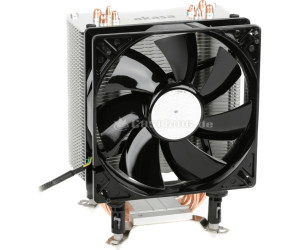
    5) The new heat sink I got for the processor is massive and the way I have it at the moment, it towers over the 4th DIMM slot, which means upgrading the system memory means turning the heatsink in a non-preferred airflow direction. I may have put on too much heat sink adhesive. I'm going to have to check this again tonight.

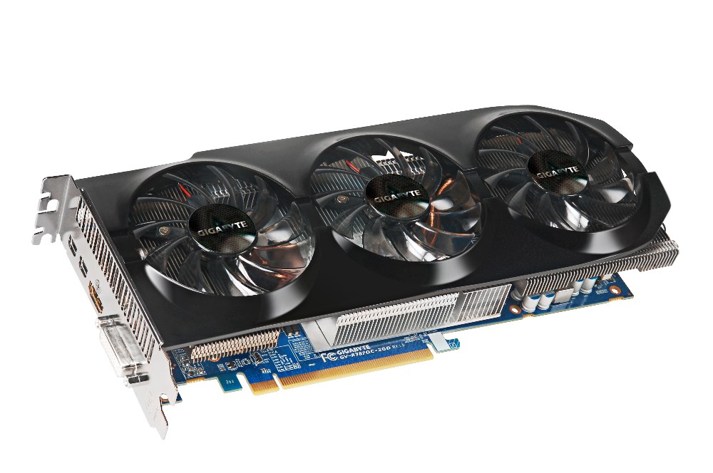
    6) The Graphics card is a monster! It hasn't gotten in the way yet, but it spread from one side of the motherboard straight across to the other side. The card itself kind of gets in the way of the USB3.0 header on the board. It takes two 3x2 PCIe cables from the PSU.
    7) My last little issue with the motherboard is the placement of the front panel headers. They're all fairly close together on one side, but it's the USB3.0 header which bugged me as it ends up crossing all the SATA connectors and was a little awkward when I installed the graphics card. See picture below.
     

    The only old components I don't need to upgrade are the Belkin PCI 802.11G wireless card, Logitech wireless keyboard and mouse, 2.1 surround sound speaker set, 1 x 500GB SATA2.0 HDD and 1 x 1TB SATA2.0 HDD.

    Useful parts that I could probably sell on are: (need to look up specifics on these)
    1) 1 x nVidia 8600GT Graphics Card
    2) 1 x 500W Power Supply
    3) 2 x 2GB DDR2 memory.
    4) 1 x Lite-On IDE DVD Drive

    eBay are having a zero insertion fee this weekend, I may try and fob them off there. I'd be more than happy to give them away to friends.

    Thursday, 11 October 2012

    My new PC

    My old desktop PC died when I moved house. I spent a whole day trying to figure out what went wrong with it. The motherboard had been acting up for a while. I put new DDR2 memory in it a while back and it caused a loud screeching sound on the audio output. I couldn't use my Creative X-Fi  sound card after a while(back in the days when sound cards were necessary for a nice sound). The card is probably still in good nick too. The built in audio on motherboards these days is just so good, it makes sound cards an option only for those recording their own music and need super high quality equipment. I'll have to upload the specs of my now dead system, just for a comparison of my move up in the world.

    Anyways, onwards and upwards, my new baby is going to be a beauty. I wanted to keep it as low as possible, but I can't seem to keep it lower than €868.51 at the moment from Dabs.ie. I wish I more to  spend, but this years been an expensive year, buying house, fixing house, getting engaged and many holidays, now I'm supposed to be saving for a wedding. I figure this is my present for my 30th :)

    Here's the setup:
    Processor: i5-3570K S1155, 3.4GHz, 6MB cache
    Processor Fan: Akasa Nero 3 premier CPU cooler (will be replaced at later date)
    Motherboard: Gigabyte Z77X-UD3H S1155, Intel Z77 chipset, DDR3, PCIe3.0 (I love the 2oz copper plane for power and ground, improves cooling, noise reduction and all round better design :D )
    Memory: Corsair Vengeance 8GB (2x4) DDR3 1600MHz, CL9 XMP
    Graphics Card: Gigabyte ATI Radeon 7870 HD, 1100MHz, 2GB, PCIe3.0
    PSU: 750W OCZ Technology Fatal1ty Series High Performance PSU
    Case: Gigabyte Luxo X10 Gaming case (Front USB3.0 and Side LED fans)

    I've got a bit of a Gigabyte theme going on here. I have to admit, I'm impressed with some of their stuff and I figure they'll complement each other in this system. I originally picked the EVGA nVidia Geforce GTX 650, but a good friend recommended against it as it would seriously impede this system. AnandTech's GPU product benchmark comparison tool is a great site for comparing GPU's against each other. The performance of the GTX 650 compares only a little better against the older GDDR3 PCIe2.0 cards. If I'm going to build a new system I want to use the latest technology.

    I know what you're thinking, where's the SSD's, where's the monitor, what about liquid cooling? These are future updates. My old systems old SATA drives are still operational and my old monitor will have to do until I can afford a nice one. My current SATA drives may be slow and small (1 x 500GB and 1 x 1TB) and will certainly be the bottleneck in the system until they're replaced, but they'll have to wait. The same goes for the monitor, it's a VGA input only monitor measuring 21inches (was big when I got it), but I'll be wanting something larger, say 24 to 27inches with a refresh rate of about 2ms, full HDMI and more. I've yet to look into these. Any larger than 27inches and I'll have to get shares in SpecSavers, am blind enough as is.

    I'll have one more crack tonight at my dead old PC to see whats working in it so I can gauge how much I can reduce the above costs. Unfortunately I'd be wary about any hardware in the old system as it was in a bad way, but if I can verify the PSU is in good nick, that could save me a €100. The power supply I've picked above is well above what I need. I used ThermalTake's PSU Wattage Calculator to calculate my systems power consumption and I got a result of 352W running at 85% TDP, so my 750W is excessive. I figure if my old PSU is good, I can keep that and leave out the new one. Even if I add a number of SSDs, SLI graphics card, I'm still under the 500W mark.

    I'll sleep on it all tonight and I'll buy it tomorrow. Hopefully there will be a Friday deal that cuts my cost down again.

    Wednesday, 5 September 2012

    My Raspberry Pi

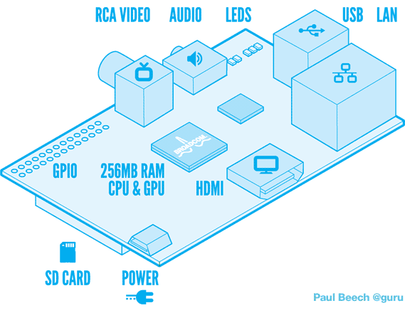
    My latest gadget arrived on my desk yesterday. I haven't had a chance to turn it on yet. It features a 10/100 Ethernet port, 2 USB ports, 1 HDMI port, 1 RCA port, 1 3.5mm audio jack, SD Card slot for the OS, 1 micro USB connector for power and a number of other not so obvious connectors.


    I've looked through the schematics and figured out what the other connectors do, what access I have and what are my current posibilities. So far I've figured there's a DSI port (Digital Serial Interface) for use with a touch screen. Nintendo DSi screens would be an example of the screen that can be used here, some other possible screens feature in the Apple iPhone or other Smart phones. There's a CSI camera connector as well, possible use could be something like the XBOX's Kinect. There's another connector which allows JTAG connection to the Broadcom SOC, which may he helpful in debug at some point, but I can't imagine it being much use without more specifics about the Broadcom BCM2835. The last connector is a large connector with GPIO's, I2C, Serial and a SPI interface as well as pins to provide 5V and 3.3V to external circuitry.


    The one difficulty I can see so far is power. The Model B variant can use as much as 1.1A from a 5V source. The power comes from a micro USB port, which most people would power from a USB port on a desktop, laptop or TV. In most cases, USB ports only provide 0.5A at 5V. If the device tries to draw more current than available, then a drop in voltage will occur, causing some parts of the device to behave outside specification. This is all mentioned on the Raspberry Pi (RasPi) forums. Looks like I may need to sort myself out with a decent power source or build one myself. That's just my initial thoughts for the moment.

    With regards what I'm going to do with it, I have a few ideas, most of which are robbed from everyone
    1. Multimedia server attached to my TV, giving me access to online streaming of videos, movies, tv series and music.
    2. Touch Screen Hi-Fi system, could be troublesome, no drivers exist yet for DSI port.
    3. Home Automation using zigbee around the house, turning on and off lights, controlling temperature, monitoring power and all that kind of thing.
    4. Serious car stereo upgrade providing music, name of song and easier use while driving.
    5. Attach a camera to allow for some sort of XBOX kinect gaming platform.
    I'll have bigger and better ideas once I turn the thing on. Watch this space :)


    Thursday, 26 January 2012

    Assignments, Masters Project and Social Media cold turkey

    I'm currently going mad trying to finish up my assignments for my 1st semester of the 2nd year of my Masters. I've had five to complete, I finally finished the first on Monday night. It was an assignment on the evolutionary product stages for Hybrid Cars and Hard Disks. My other assignments are a solution to the water distribution problem using innovating problem solving techniques. The other two assignments are based on research techniques using nVivo and SPSS. The final assignment, the killer one, which is soaking up all my time, is the implementation and optimization of a microprocessor and an SRAM on a BASYS 2 board. This last one is proving a serious challenge as my first real application in an FPGA. On the other hand, I've been secretly enjoying it.

    On a very positive note, I've finally decided on what I want to do for my final year project. I found a great article in last month's IEEE Spectrum on the implementation of Crypto-Accelerators. The article provides plenty of research material and the topic seems really interesting to me. I'll post more on this once I finish my assignments and I can actually put some time on it.

    On another note, I've decided to go cold turkey on social media in work. At first it started off checking Facebook during lunch, then the odd tweet every now and again. I got addicted though and it got worse, my productivity went down and it was horrible. So I've been two months clean, I edited the hosts file (computer file used in an operating system to map hostnames to IP addresses) in the Windows directory to block myself from drifting back. Since then I've been more productive, I've started to manage my time better and organise myself.

    I can't wait until I'm finally finished these assignments. I'm off snowboarding with my friends to Avoriaz on the 4th February for a week. I really can't wait.

    Now back to my laptop and the Xilinx ISE to create my testbench, simulate and script my verilog microprocessor.

    Friday, 25 November 2011

    New Business selling SnowSocks, doing a Masters and everything else


    I've been incredibly busy the last while. There's a small part of me thinking I might be stretching myself beyond what I can possibly handle. But I think I'm well able for all of it. Who says you can't start up a new business while working a full time job and doing a part time Masters at night in Electronic Design Engineering?

    My Masters has been proving very interesting so far. This semester I'm studying Digital Synthesis Modeling as well as Research Development Techniques and Problem Solving. For the Digital Synthesis Modeling, I've been using a Basys2 reference board to learn how to program in both VHDL and Verilog. The first three assignment proved difficult enough and a great basis for the fourth (capstone) assignment. The first three were: 1) Led flashing 2) Sequence Detect using switches and buttons 3) Implementation of Seven Segment display. The fourth assignment is the truly interesting one though. We have to design and implement a uP (microprocessor) connecting to an onboard SRAM, that sends and recieves data to and from the SRAM. This will prove difficult and may not even be possible on the Basys2 Board. Sure we'll see what happens. We also have to learn to script using command line scripting in DOS, Perl and TCL for complete automation of the synthesis process.

    The Research Development Techniques and Problem Solving module has also proved very interesting and is a welcome break to all the technical work in the digital synthesis modeling. For the problem solving, we've looked at problem solving techniques including TRIZ, the nine-windows, 40 inventive principles, the contradiction matrix and many many more. We were also given a KAI test and I got a result of 95, which means I'm equally Adaptive as I am Innovative. I'd have to give loads of references here on what exactly that means, but I don't have time for that.

    My new business venture has proved very very interesting. From ordering my stock from overseas, to customs and VAT, to advertising, marketing and selling at the markets, I have learnt so much so far. I still have a lot more to go as well. So far it's going really well and I hope to increase my sales in the coming weeks. I'm basically selling snow socks.

    Here's my companies website (http://www.snowtyregrips.com) have a peak, I appreciate any and all feedback on the site. I appreciate it even more if you purchase one of my top quality snow socks from me.

    I'll write more about the difficulties I found setting up the business and everything over the coming weeks, maybe over christmas I'll have time to write this all up.

    Friday, 9 September 2011

    Pension on Hold and Learning about Money!

    Yesterday I requested my pension be put on hold indefinitely. Our account manager was none to happy about this and reminds me that I'll lose out on my company contribution and my tax relief. This a load of sales crap in my opinion. Now I don't claim to know a lot about how they work, but the company contribution at the moment is tiny, about €16 per month, I'm ok with losing that, no biggie. The tax relief thing is a bit of a sales pitch as well. Sure I don't pay tax on it now, but when I claim my pension back when I'm older, I'll have to pay that tax back (probably at a larger rate than now, looking at how the tax rates keep climbing). So basically, it's only really a deferral of tax payments.

    Once the hold is placed on my pension, I asked for a copy of my current pension details. I've only been paying into my pension for about 16 months now, my total contributions are about €2800 and the current value is €2600. So, while I've been paying into my pension, my pension fund manager has been losing it. Seems like a wise choice to leave the pension completely. Why pay to lose money? They get paid regardless, for playing around with my money.

    My goal is to use the extra income from my pension and make it grow for me. I've a long way to go with learning about stocks, shares and investing, but I hope to blog a bit about it and what I've done so far.

    At the moment, I've been reading a few interesting books. These include:
    Rich Dad Poor Dad by Robert Kiyosaki
    Rich Dad Poor Dad 2: Cashflow Quadrant by Robert Kiyosaki
    Think like a Champion by Donald J. Trump
    The Art of War: Sun Tzu
    The Winning Investment Habits of Warren Buffett and George Soros: What You Can Learn from the World's Richest Investors

    I've also been playing Cashflow 101 (a board game about money and personal finance) with a few friends. You play as a rat in the rat race and the premise of the game is to break out of the rat race. You get a budget sheet where you keep track of your income, expenses and investments. The only way to break out of the rat race is to get your passive income to exceed your expenses each month. You're passive income consists of dividends from shares, cash made from rental properties and other investments. It's a great game and I'vhttp://www.blogger.com/img/blank.gife learnt a few things from the two games I've played already. Majority of the terms, properties and opportunities are all American based, but the lessons learned are the same. Basically, don't lose money.

    On another note about money, I've been experimenting with Trading and I downloaded a demo account for Forex Trading, through ShareWatch's website. I had a brief goof around with it last night. You get 50,000 in your balance to start off with and you can buy and sell shares based on the real market at the moment. There's a huge number of options to choose from when viewing the graphs (looking at line graphs, max/min lines, candlesticks) and you can set up your own strategies for buying and selling and give you alerts when to sell and when to buy using the likes of MACD and DMACD and a number of other strategies. It was interesting. I was only able to buy and sell currency symbols and to be honest, it just feels like gambling. Like a good mate of mine says, it's 50/50, it's either going to go up or it's going to go down. There's as much prediction in this as there is in palm reading and horoscopes.

    I'm trying to learn as much as I can and I'd love to hear what other people think about these books and the board game and their experiences with investing, so please feel free to comment below. Just keep it relevant and to the point.